Development of custom electronic boards with CNC Router.
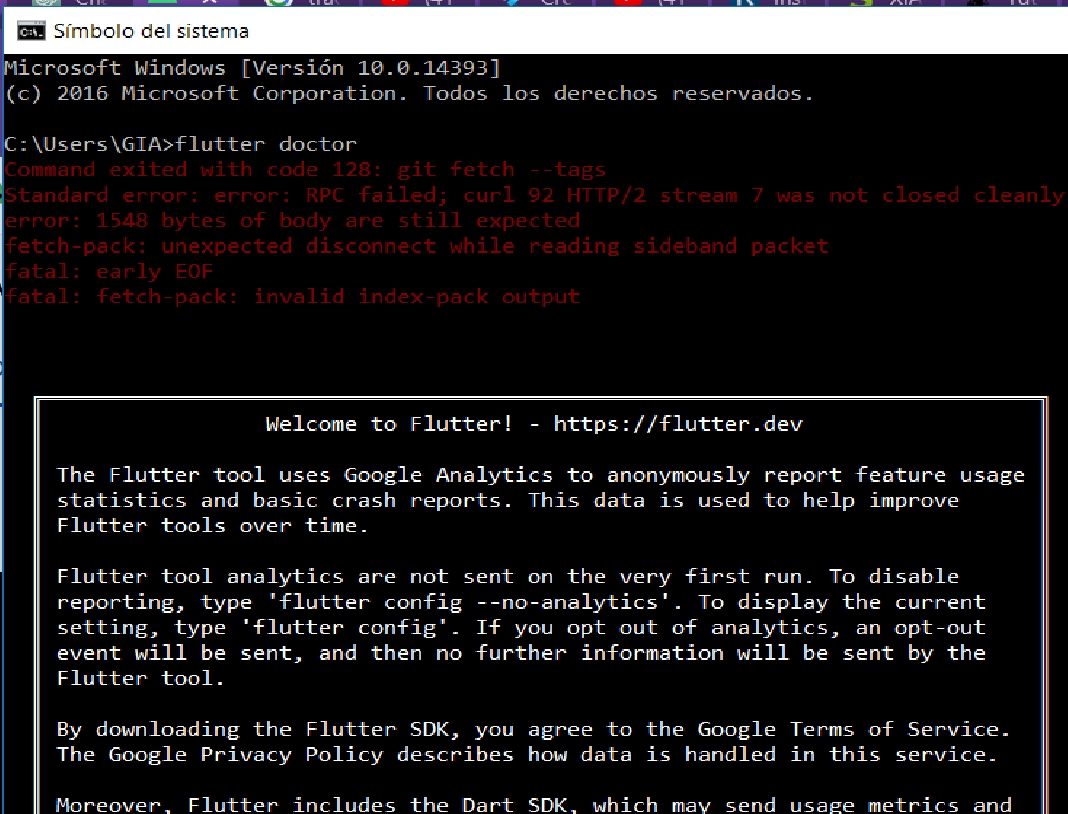
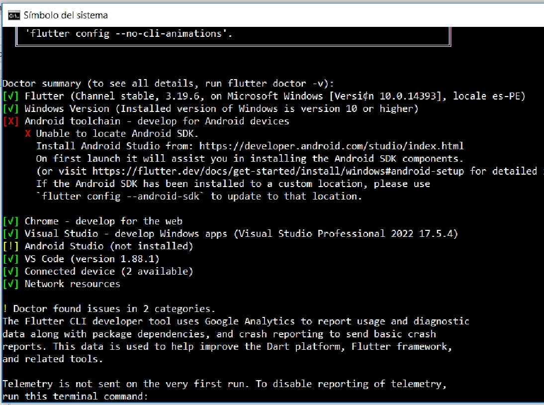
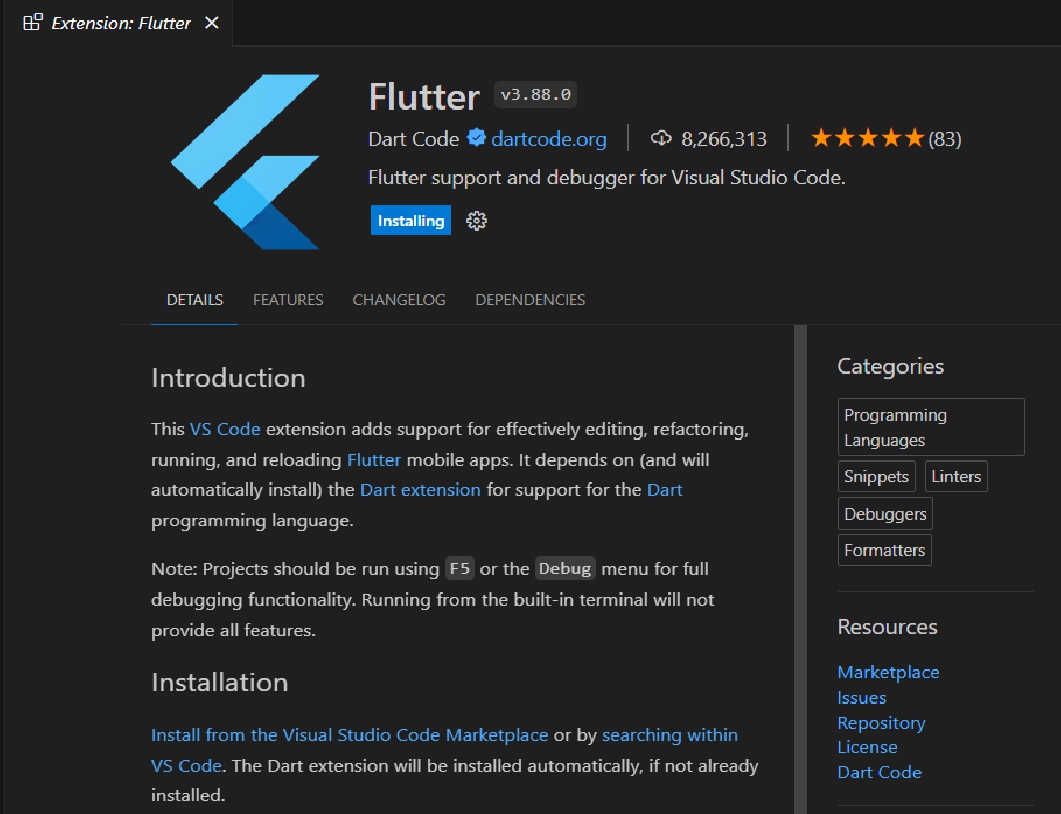
For our group project, we decided to carry out an exhaustive study of different programming languages. Personally, I focused on learning Flutter, a cross-platform mobile app development framework. This experience turned out to be very enriching, as I was able to delve deeper into the development of interactive and efficient user interfaces for mobile devices.
The process involves downloading the Processing installation file from the official website. Then, using the command line (CMD), we navigate to the location of the downloaded file, unzip it, and run the installer to complete the installation of Processing on the system. Once installed, we can verify the installation by opening the program from the command line. This method is useful if you prefer to work with the command line or need to perform the installation remotely or automated.
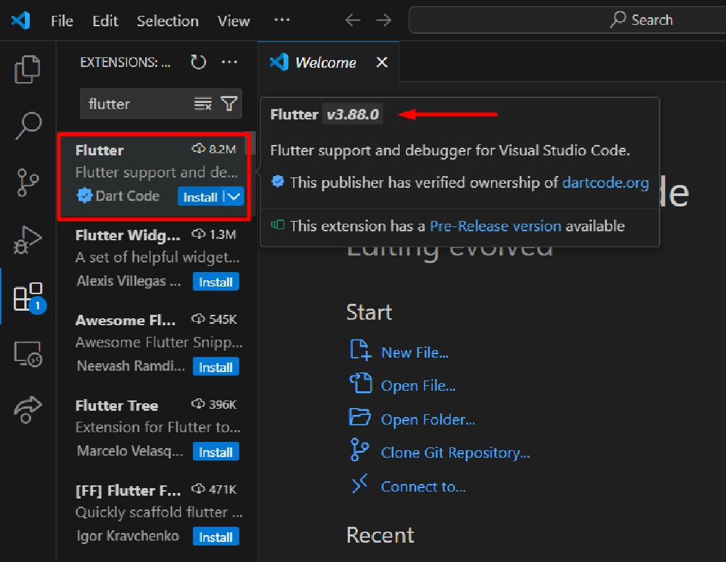
After installing Processing and if you want to work with Visual Studio Code (VS Code) as your development environment, the next step would be to install the Processing extension or plugin for VS Code. This will allow you to write and run Processing code directly from VS Code.
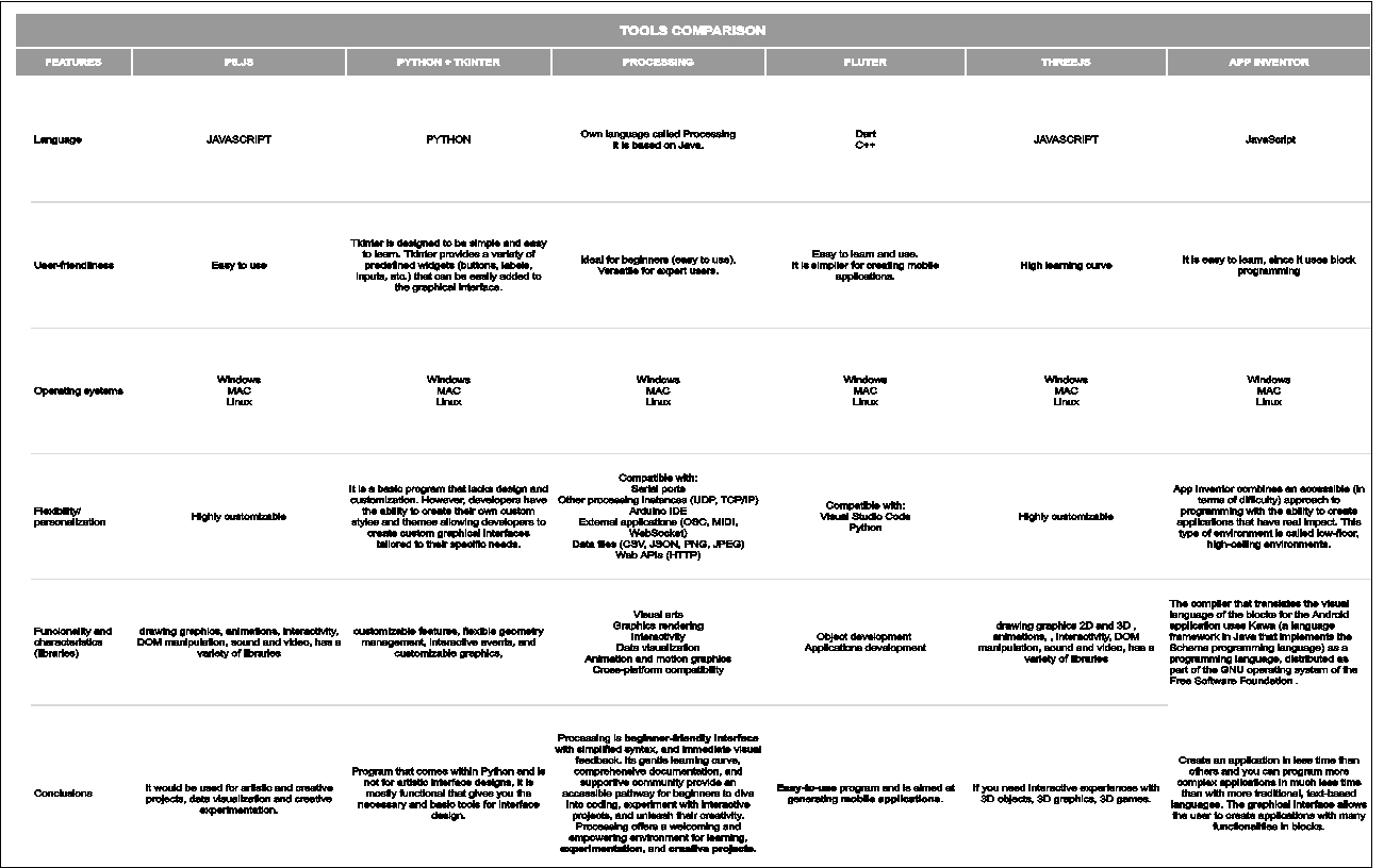
For this week's task, we were studying a language as a team and we explained its benefits. Each of us shared what we learned and we created a comparative chart.
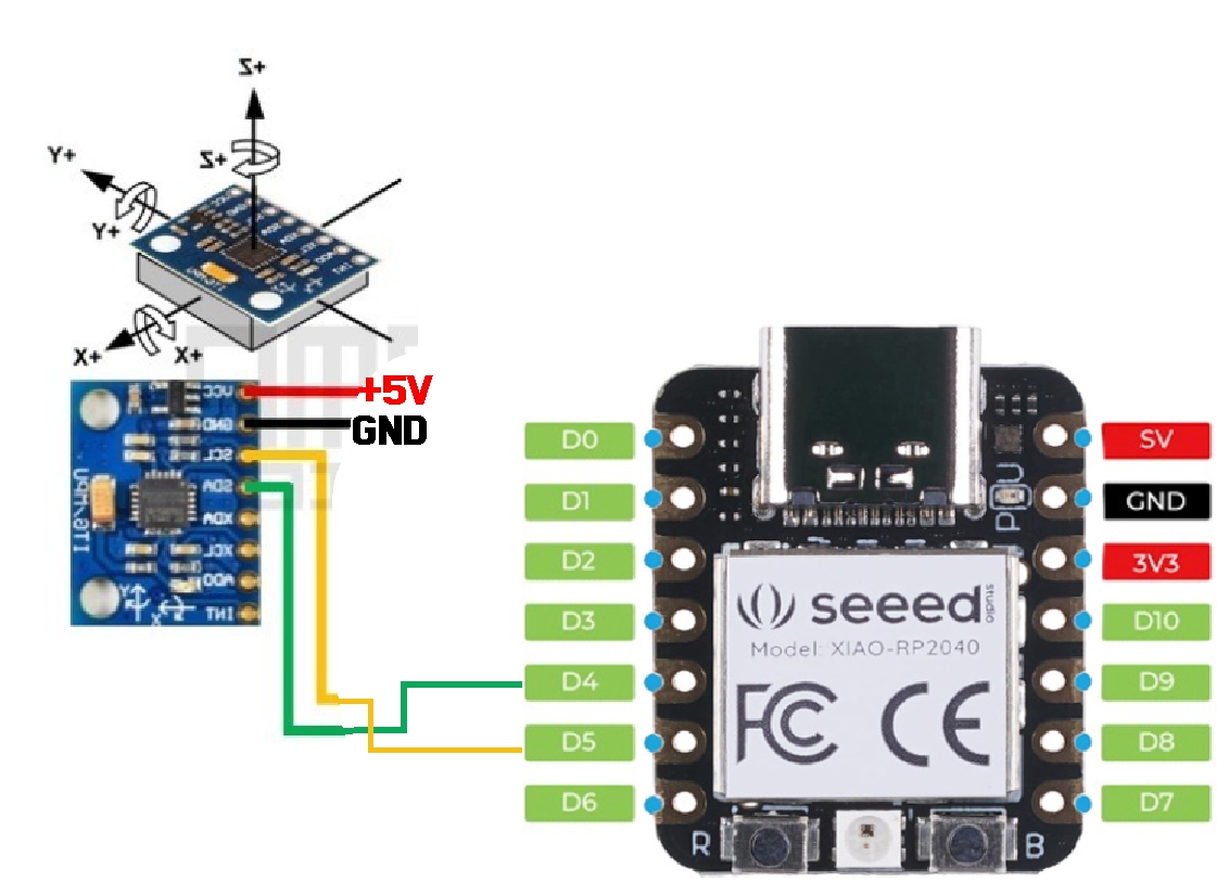
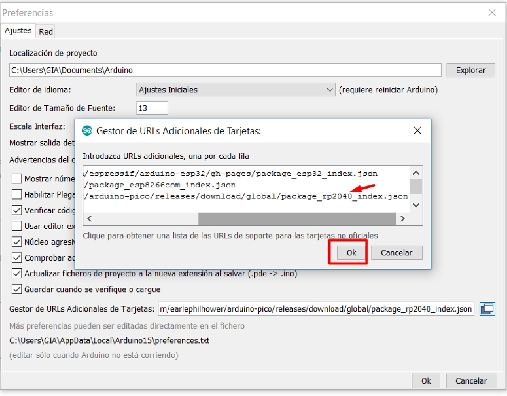
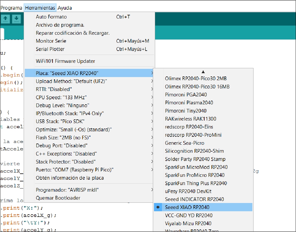
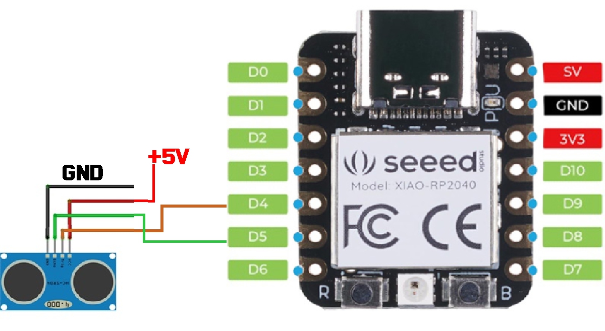
For your individual project, I would recommend using the XIAO RP2040 along with sensors like the MPU6050 and HC-SR04. Additionally, you can use Processing software to visualize interactions with these sensors. Here I detail the steps you can follow:
During our teamwork, we actively shared and discussed what each of us learned. This collaboration not only strengthened our individual knowledge, but also allowed us to integrate diverse skills and perspectives into our joint project. Through this experience, we managed to unite our efforts and create a more complete and solid work.
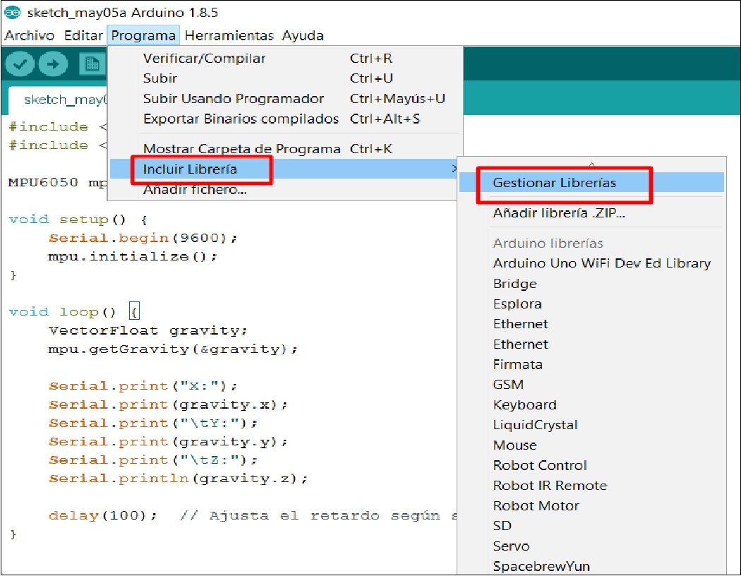
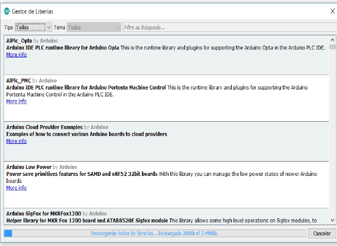
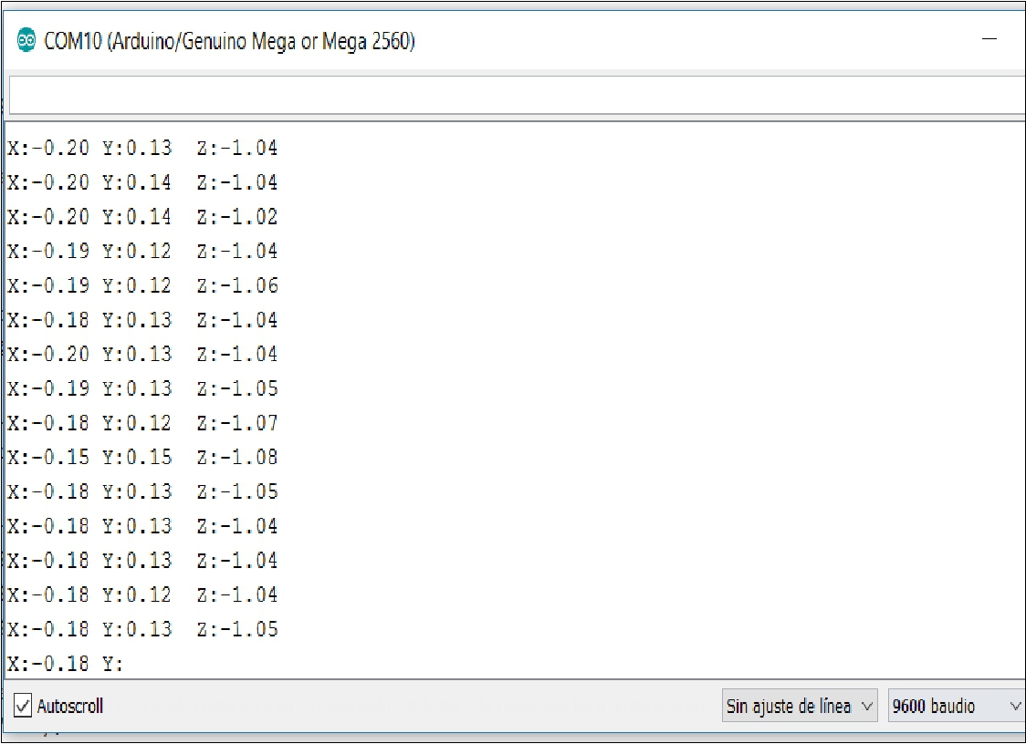
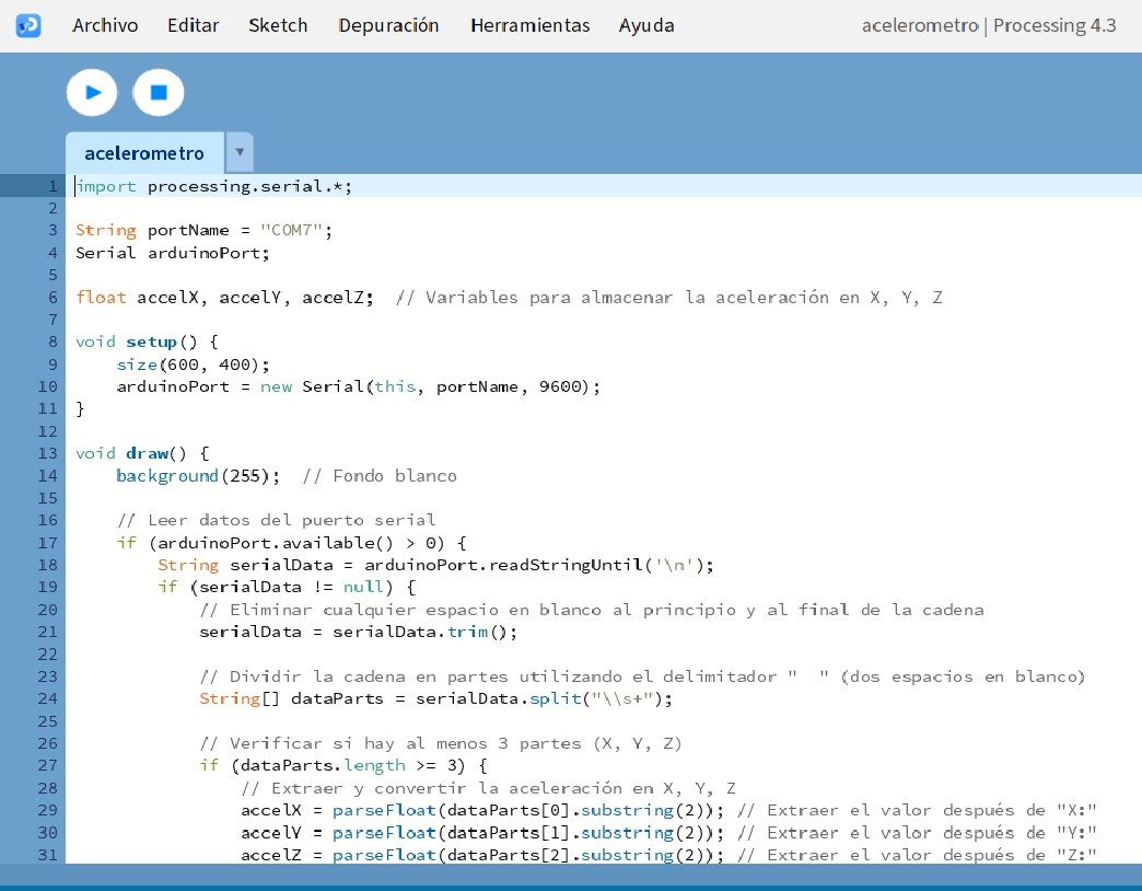
First, make sure you have MPU6050 sensor connected to your Arduino board correctly. Use the necessary libraries to communicate with the MPU6050 from Arduino. You can use the Wire.h library for I2C communication and the MPU6050.h library to interface with the sensor.
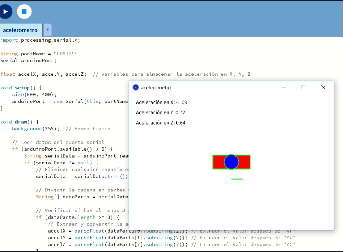
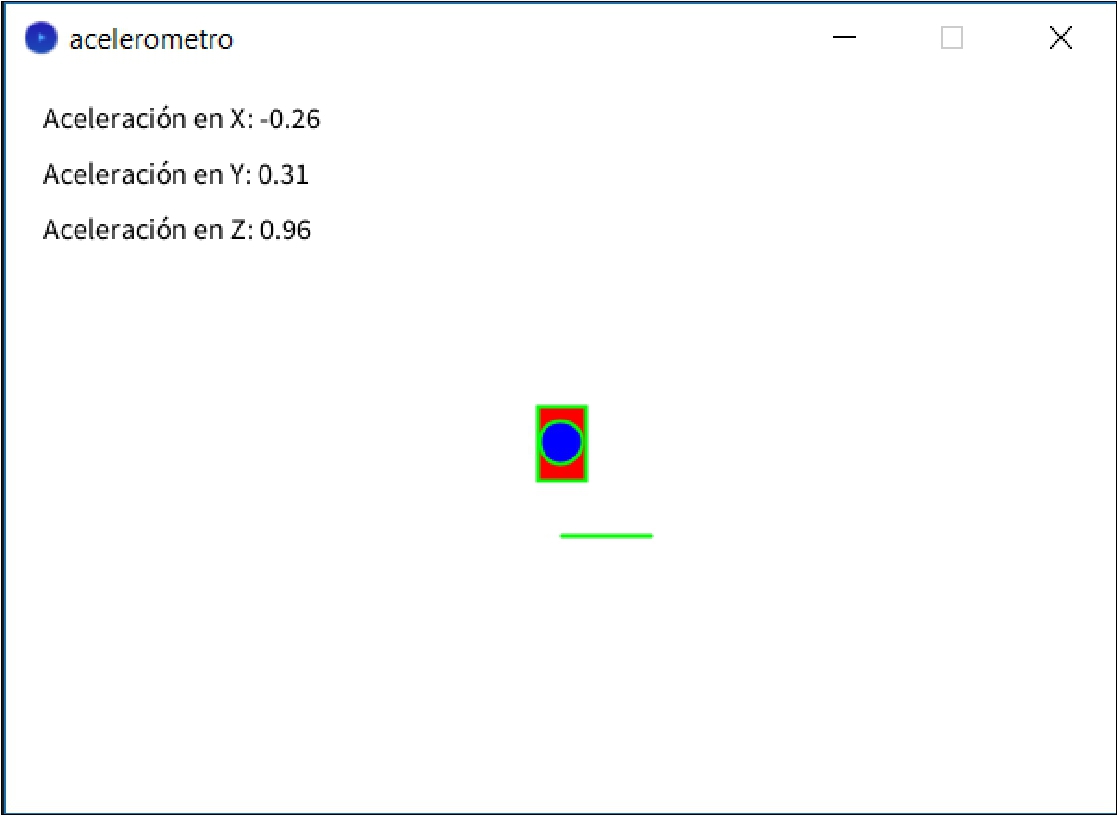
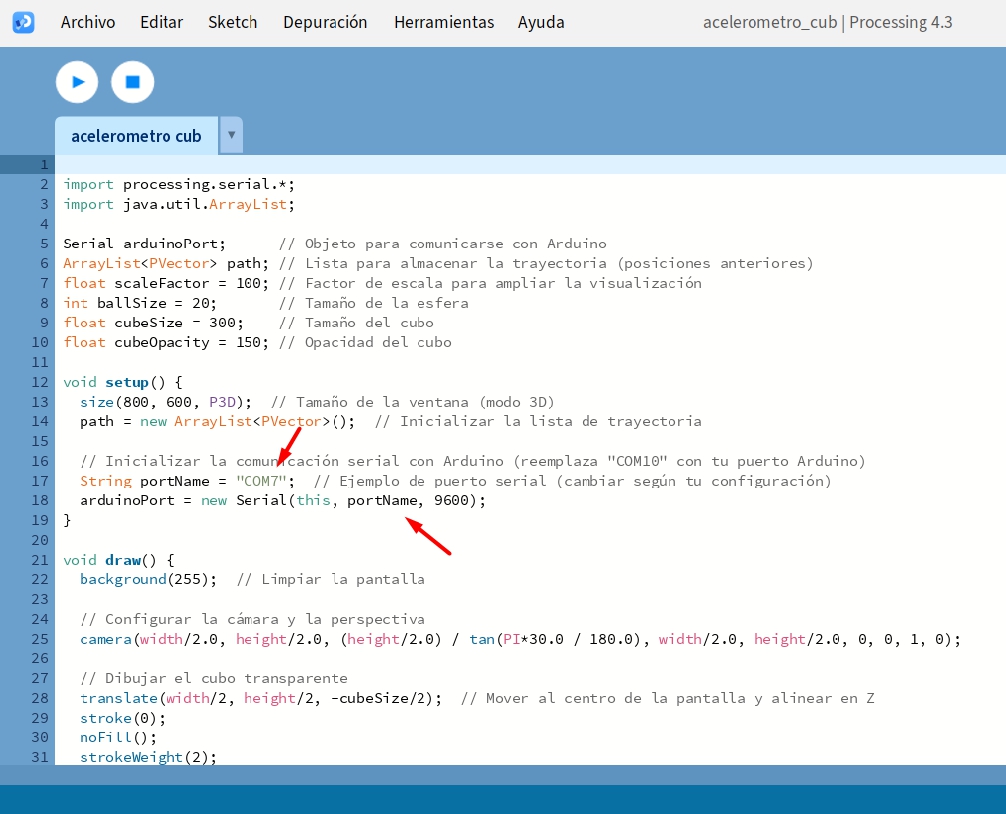
To reflect acceleration data in X, Y, and Z on a graphical platform while the program is running in Processing, you can use simple visualization shapes like rectangles or ellipses that move according to the data values.
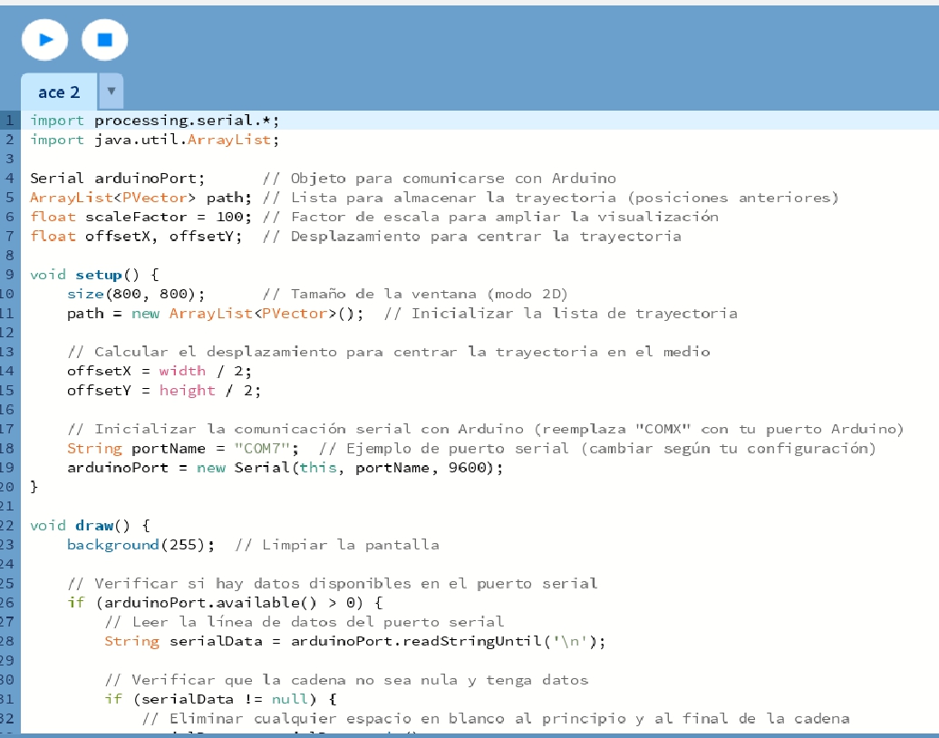
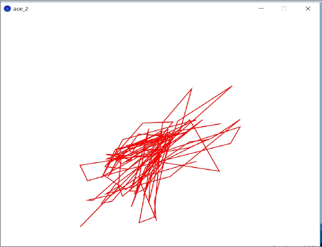
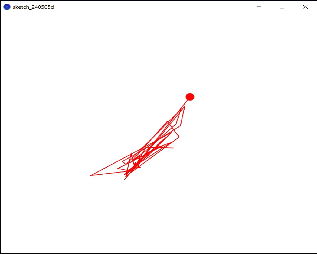
You can adjust the scale of the x and y values received from the serial port to enlarge the display in the window. For example, you can multiply values by a scaling factor to increase their on-screen size. This will allow you to see the trajectory better even if the values are small.
Center the Path in the Middle: To ensure that the path is centered in the middle of the window, you can adjust the x and y coordinates when drawing points and lines. Subtract half the width and height of the window from the x and y coordinates respectively to center the path
If you want to represent movements instead of points as a ball moving along the path generated by the data received from the serial port, you can modify the code to draw and move a ball (ellipse or ellipseMode(CENTER)) in instead of using lines or points. Here I show you how you can adapt the code to achieve this effect
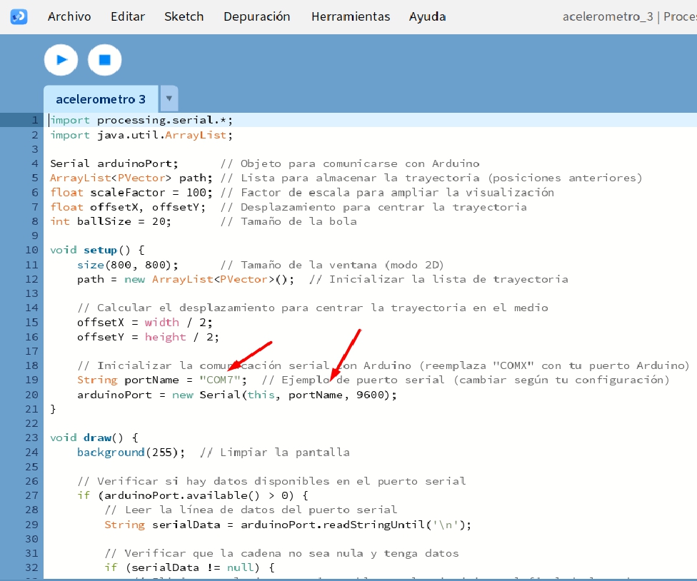
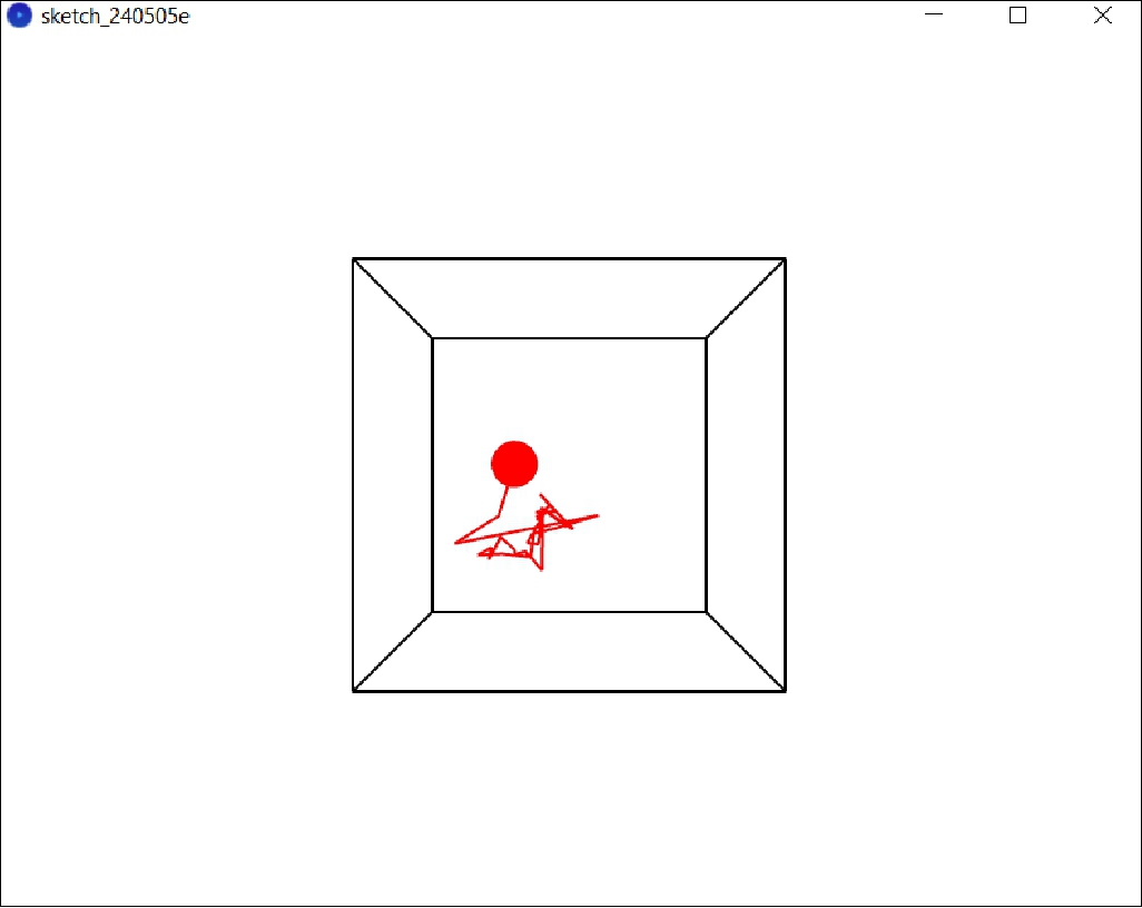
Here is an improved version of the code that focuses on displaying the sphere representing the movement inside the cube and tracking the trajectory in real time
In Processing to track the elapsed time and display the distance during that interval. Here's how you can set the code to display the distance for 2 seconds after receiving new data from the serial port.
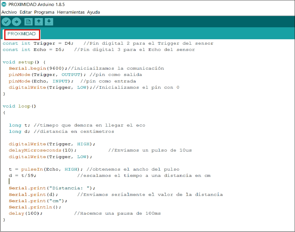
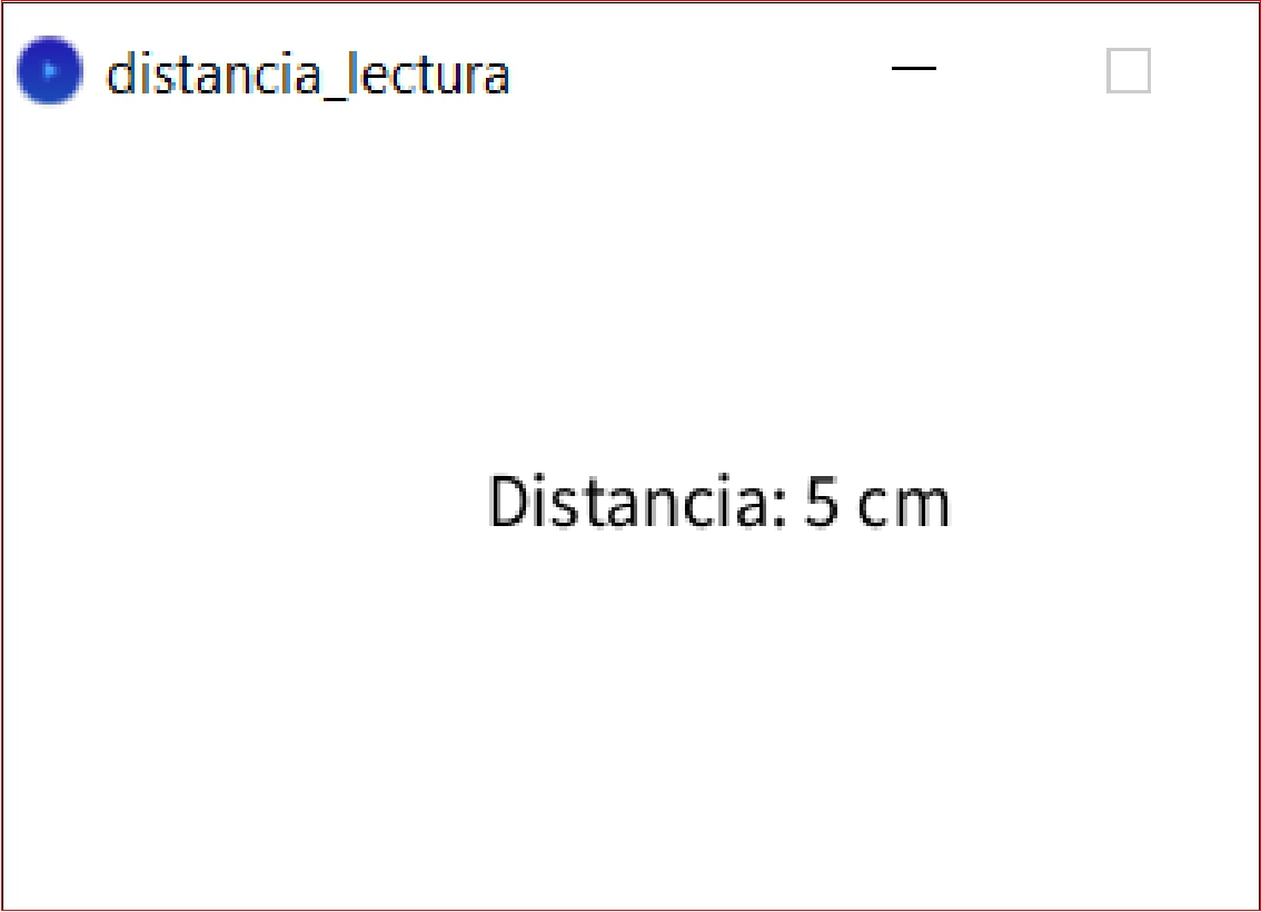
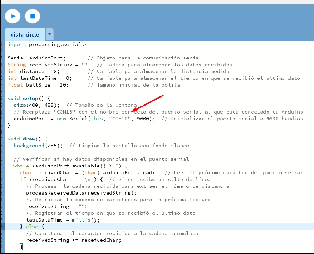
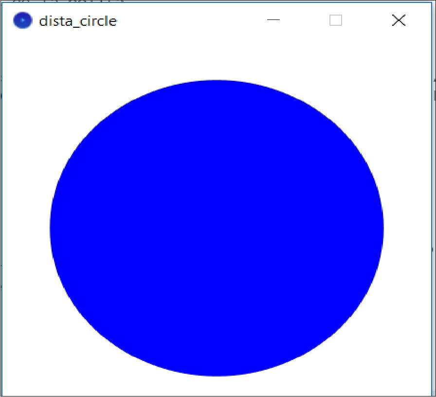
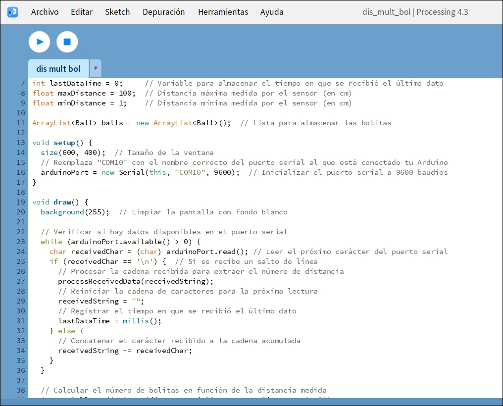
To have a ball drawn in the center of the window and change size as you move closer or further away from the distance sensor connected to the Arduino, you must modify the code so that the position and size of the ball are dynamically updated in function of the measured distance. Here I provide you with a modified version of your code in Processing that includes the graphical representation of a ball in the center of the window. The size of the ball will change depending on the distance measured by the ultrasonic sensor connected to the XIAO RP2040
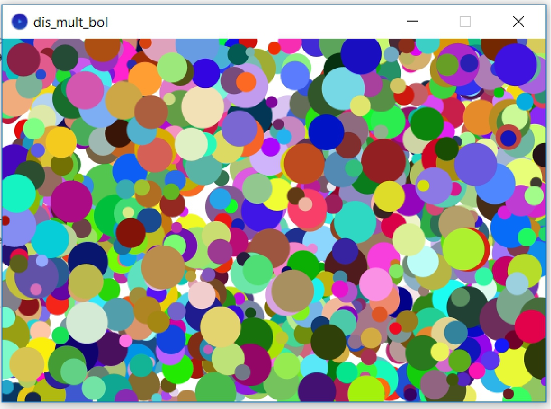
To create an effect where the number of beads increases as you get closer to the distance sensor, you can modify the code to generate more beads when the measured distance is shorter. Each ball will have a size proportional to the distance and will appear in a random position around the center of the window.
During this week, I learned how to use an interface to interact in real time with sensors, allowing multiple sensors to be controlled at the same time using a microcontroller such as the Seeeduino XIAO. This knowledge opens the door to various applications that we can develop using different sensors. As of week 14, I've explored several programming languages, which has been a lot of fun. Although at first it was a little tedious, with practice I have managed to feel more comfortable and competent in developing projects with these devices.
Development of custom electronic boards with CNC Router.
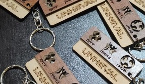
Development of personalized keychains and ornaments with CNC Laser.
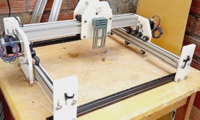
Development of custom machines "Desktop CNC Laser.

Huánuco is a Peruvian city, capital of the district, province and department of the same name in the north-central area of the country. The city has a population of 235,529 inhabitants. .